
USB-C to HDMI Reliability Over Time: Cable Length, Wear, and Stable Connections
USB-C to HDMI connection reliability is about how consistently a cable, adapter, and port combination maintains a stable video signal over its service life. Over time, users often encounter observable symptoms such as flicker, brief blanking, and signal dropouts—clear signs that the physical link is no longer delivering the same steadiness it once did, and these outcomes are the main way to assess connection stability.
Connection instability often stems from two broad categories: signal margin issues related to cable length and interference, or contact and wear issues from connector degradation. The physical drivers behind these categories include progressive wear on connector contacts, reduced signal margin in longer cable runs, and accumulated strain on internal conductors. Cable motion near the junctions can create micro-fractures, while repeated insertions may loosen the fit between the plug and port, leading to a loose connection that can cause intermittent on-and-off behavior.
Environmental factors such as heat, humidity, and dust further degrade contact quality. The timeline and severity of these issues often depend on cable path, handling, and environment.
USB-C to HDMI reliability over time depends on three maintenance levers that you can influence directly:
- Sensible length choice – shorter cables generally preserve better signal margins and are less vulnerable to interference; longer runs become more sensitive to noise and motion.
- Reduced mechanical stress – minimizing cable motion at the connector and using strain relief support can slow connector wear and prevent a loose fit.
- Early symptom recognition – noticing flicker or dropouts early can allow you to inspect and replace the cable before the problem escalates.
Physical wear and loose connections are common sources of instability, but not every glitch indicates a fundamental compatibility breakdown; in many cases, the issue stays within the cable-path layer—connectors, plugs, adapter, and ports—rather than requiring adjustments to device settings or resolution tuning. Distinguishing true reliability degradation from other interference sources starts with recognizing how an ageing physical link behaves.
Reliability signals in a USB-C to HDMI connection
USB-C to HDMI reliability refers to consistent display output and stable link behavior during normal handling, as long as the physical setup remains undisturbed and the components are in good condition. These reliability signals are most relevant to cable length and physical wear rather than full setup procedures. Normal handling includes typical cable movement, device placement, and connector insertion without excessive force.
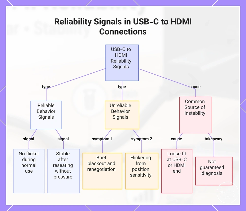
Reliable behavior looks like a steady image that typically does not flicker or briefly black out when the cable is moved lightly. Intermittent connection issues often appear as a brief blackout followed by a renegotiation cycle, or as flickering when the cable is in a position‑sensitive state. A loose fit at either the USB‑C or HDMI end is a common source of such instability. Reliability signals in a USB‑C to HDMI connection include observable behaviors that indicate a stable link or a developing issue. However, symptom ≠ single cause. These signals guide maintenance, not guaranteed diagnosis. For a broader overview of which devices and adapters work together, see the USB-C to HDMI Compatibility hub.
- Consistent display without flicker during normal use
- No brief blackouts when the cable is moved slightly
- Stable link after a connector is fully reseated
- No intermittent connection when the cable is in a typical position
- Normal operation without pressure being applied to the connector
This chart shows the main reliability signals for a USB-C to HDMI connection, including reliable behaviors, unreliable symptoms, and a common cause of instability.
Where instability comes from in the cable–adapter–port chain
Instability can come from any point along the cable–adapter–port chain. The three main segments are the cable itself, the junction where cable meets adapter or hub, and the USB-C port fit where the connector inserts. Movement, routing, and repeated plugging affect each segment differently, so localizing the cause class helps decide whether maintenance or replacement is the appropriate action.
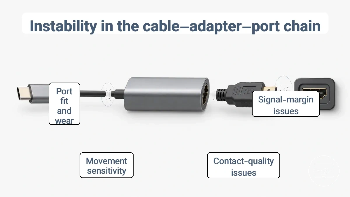
The root causes of instability fall into two classes: signal-margin issues and contact-quality issues. Signal margin refers to the electrical headroom available for a clean transmission; losses increase with longer cable runs and higher interference, especially at junctions. Contact quality refers to the physical fit and wear at each connection point. Movement sensitivity, contact wear, and poor port fit degrade contact over time. However, a single symptom like a flickering screen does not point to only one cause class; both margin and contact problems can produce similar interruptions. The two classes are margin-driven and contact-driven instability.
- Margin-driven instability – triggered by longer cable runs, interference from nearby signals, or weak source output. Symptoms may appear under high data rates or when the cable is moved near other cables.
- Contact-driven instability – triggered by repeated plugging, dust in the port, or a loose connector fit. Symptoms often appear when the device is jostled or when the cable is reinserted.
If the connection fails when the cable is moved, the likely cause is movement sensitivity at a junction or port. If the failure occurs without movement, signal margin or interference may be responsible. Where instability comes from in the cable–adapter–port chain, this checklist orders checks by chain location to isolate the cause before moving to length or wear-specific checks.
- Check the cable segment for kinks or fraying near the connector because it can cause intermittent contact loss.
- Check the junction between cable and adapter for a loose connection or dust because it can introduce signal interference.
- Check the USB-C port on the source device for debris or bent pins because it can reduce port fit and cause movement sensitivity.
- Check the adapter's video output port for wear or poor pin alignment because it can degrade contact quality.
- Check the entire cable run for proximity to power cables or magnetic fields because it can trigger margin-driven instability.
Cable-Side Causes: Conductor Fatigue, Shielding Degradation, and Plug Fit
Conductor fatigue, shielding degradation, and plug fit are three cable-side mechanisms that can gradually reduce display stability even when devices and settings do not change. Repeated bending and routing can cause conductor strands to weaken, shielding to lose its noise protection effectiveness, and connector fit to loosen.
Each cable-side attribute corresponds to a typical symptom pattern:
- Conductor fatigue from repeated bending may produce intermittent dropouts when the cable is flexed.
- Shielding degradation can allow interference to reach the signal, causing flicker during movement or when routed near other cables.
- A worn plug fit may cause position-sensitive symptoms, such as intermittent reconnect when the cable is jostled or repositioned.
Adapter and hub contact points that age differently than a direct cable
Adapter and hub contact points age differently than a direct cable because they introduce extra junctions where wear, oxidation, and movement can accumulate. Each junction degrades independently. Unlike a direct cable with fewer junctions, an adapter or hub path has multiple such points, and these extra contact points are a key variable in stability.
When a connection starts to fail intermittently after months of use, the cause may be gradual degradation at the adapter or hub contact points rather than the cable itself. Oxidation or contamination can increase resistance at these junctions, and looseness from repeated plugging can create play that leads to an intermittent connection. The stability outcome depends on the design and quality of the adapter or hub; some designs use better materials or locking mechanisms that reduce movement. This variation across designs is covered in how solution type affects stability.
Adapter and hub contact points age differently than a direct cable, as summarized in the table:
| Path Type | Reliability Sensitivity |
|---|---|
| Direct cable | Fewer junctions; stability depends mainly on cable integrity and connector quality. |
| Adapter/hub | Multiple junctions; each contact point adds potential for oxidation, looseness, and intermittent connection. |
How Cable Length Changes Connection Stability Under Real Use
Longer USB-C to HDMI runs can reduce stability by shrinking signal margin and increasing sensitivity to interference and motion. A cable that works fine at a short, fixed length may develop intermittent dropouts or flicker when the same run is extended, routed near power sources, or moved. The same cable may behave differently depending on whether it stays in a stationary desk setup or is moved between locations.
Consider a cable routed behind a desk alongside other power cables and then occasionally bumped or shifted. The combination of reduced margin and added interference from nearby wiring can cause sporadic blank screens or flicker. When the same cable is coiled tightly in a travel bag or bent around sharp corners, the physical stress on the connector and cable itself can further reduce tolerance to movement and signal loss. These real-use conditions — routing, interference sources, and handling — influence whether a given cable length remains stable or becomes unreliable.
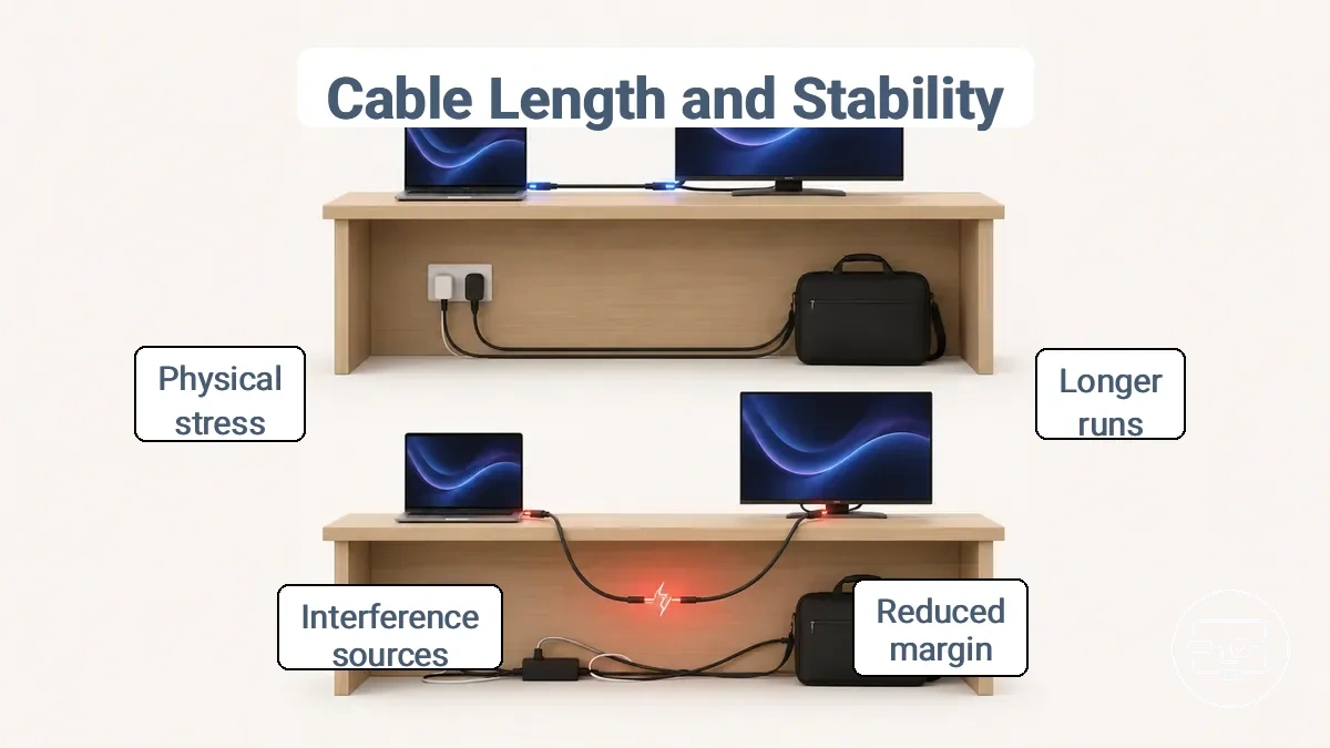
This diagram shows how routing and interference affect stability for different cable lengths. The table organizes length-related risks by common use environments, showing how cable length changes connection stability under real use. Each environment introduces different stress factors that can reduce signal margin and trigger symptoms.
| Use context | Length-related risk factor | Typical stability symptom |
|---|---|---|
| Desk-stationary setup | Moderate length with cables bundled together | Occasional flicker when nearby devices power cycle |
| Travel bag or portable use | Longer cable coiled or folded under stress | Sporadic signal loss after moving |
| Tight routing behind furniture | Sharp bends and pinch points reduce margin | Persistent flicker or blank screen at certain angles |
| Near power adapters or bricks | Proximity to electromagnetic interference | Random dropouts when adapters are active |
| Frequent plugging/unplugging | Connector wear and repeated flex at the joint | Increasing connection instability over time |
Longer cable runs do not always fail, but they are less forgiving of imperfect routing, interference, and movement. Understanding how these environmental factors interact with cable length explains why longer runs tend to fail first, even if the cable itself is otherwise functional.
Why longer runs fail first: margin loss, interference, and movement sensitivity
Why longer runs fail first: margin loss, interference, and movement sensitivity. Each mechanism amplifies a different set of symptoms, though which one dominates depends on the setup and environment. Longer runs are more sensitive to these factors but are not inherently unreliable.
- Margin loss becomes noticeable when the signal weakens over distance, especially near length limits. Tight bends in the cable routing can accelerate this loss, often resulting in flicker or a black screen.
- Interference happens when the cable runs close to power lines or other sources of electrical noise. It may introduce signal corruption and cause dropouts, particularly in rooms with dense wiring.
- Movement sensitivity can make the connection unstable when the cable or connector is touched. This is a common trigger for intermittent connection problems, such as dropouts or reconnect cycles.
Choosing length to reduce flicker and intermittent dropouts
Choosing a practical length reduces flicker and intermittent dropouts because it keeps the connection within a safer margin for signal stability. A shorter cable that matches your actual desk setup minimizes slack, simplifies routing, and reduces strain on the connector. Use these criteria to confirm that your length choice supports stability rather than introduces new failure points.
- Choose a length as short as practical for your fixed desk distance to reduce flicker from signal degradation.
- Leave moderate slack for movement without pulling the connector, which can cause intermittent dropouts.
- Avoid tight bends near the connector to prevent internal wire strain that may lead to flicker.
- Route the cable away from power cables to reduce electrical interference that may cause dropouts.
- Support the cable weight near the port to reduce connector torque and maintain stable contact.
- Reduce the number of sharp turns in the cable path to maintain signal integrity and avoid intermittent dropouts.
Physical wear that leads to intermittent USB-C to HDMI connections
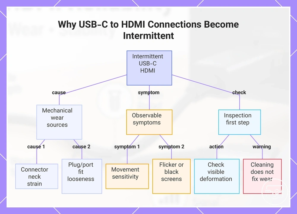
Intermittent behavior from a USB-C to HDMI connection usually stems from mechanical stress and contact degradation, not a sudden total failure. Repeated plugging, side-load, and everyday handling gradually strain the connector neck, loosen the plug-to-port fit, and deform the cable body. These three wear zones — connector neck, plug/port fit, and cable body — are where physical wear first shows up as flicker, signal drop, or a display that cuts out when the cable is moved.
When a cable has been used for months with frequent plugging and unplugging, the strain relief at the connector neck can stiffen or crack, transferring force directly to the internal solder joints. A loose fit inside the port — where the plug wobbles or needs to be held at a certain angle to work — is a strong sign that the metal shell or latch has deformed. This repeatable movement sensitivity, where the connection works when held in one position but fails when nudged, is a clear sign of wear-related looseness.
Question: Can a loose USB-C connector cause intermittent HDMI?
Answer: Yes, a loose fit inside the port can break the display signal when the cable is moved or when the device is bumped. Inspecting the connector and cable for visible deformation or stiffness is the safe first step before considering replacement.
Question: Does cable wear cause flicker?
Answer: Cable wear, especially at the strain relief and wear points, often produces flicker or brief black screens because the internal conductors lose stable contact under slight movement. Examining the connector and cable for visible deformation or stiffness is a safe first step before considering replacement.
A common myth is that cleaning the port or plug can fix a loose connection caused by wear. While debris can sometimes mimic looseness, cleaning does not restore deformed metal or worn strain relief. Wear checks are observational — they identify visible damage and movement sensitivity — and do not replace deeper symptom-specific fixes handled elsewhere, such as driver updates or resolution adjustments.
This chart explains how physical wear causes intermittent USB-C to HDMI issues, the observable symptoms, and the first inspection step.
Strain relief failure and bend damage near the connector
The strain relief zone at the connector neck is a high-stress transition area where cable movement can lead to intermittent failures. Bends, pulls, and coils concentrate force at this junction rather than spreading along the cable. Repeated flexing can fatigue copper strands or weaken internal connections even when the outer jacket shows no visible wear, meaning damage can be internal even if the outside looks fine.
The following handling patterns often lead to strain relief failure and bend damage near the connector:
- Frequent coiling near the plug neck applies repeated bending force to conductor strands, leading to internal fractures that often appear as movement-triggered flicker or intermittent dropouts.
- Pulling the cable by the connector housing transmits tensile load through the strain relief area, which can damage solder joints and cause signal loss when the cable is repositioned.
- Sharp bending at the connector neck during use or storage concentrates stress on insulation and conductors, producing intermittent connectivity that can appear when the cable is moved to a different angle.
- Repeated coiling and uncoiling forces the strain relief to flex beyond its intended range, gradually fatiguing internal wires, which can result in flicker or dropout symptoms not present when the cable is straight.
Loose Connection from Repeated Plugging and Side-Load Stress
Repeated plugging and side-load stress can reduce contact firmness at the plug-port interface, resulting in position-sensitive signal dropout even when the cable body looks intact. Over time, this can create intermittent partial contact that may work in one position but fail in another. Side-load refers to sideways force applied to the plug after insertion, often from cable weight or routing, which can further destabilize an already loose fit.
A cable that works only when held at a certain angle or propped in place often indicates physical looseness rather than a setting or driver problem. When exploring loose connection fixes, the first step is often to reduce side-load, support the cable weight, and confirm the fit rather than changing software settings. Observing the connection's behavior under different cable positions—without applying extra force—is a safer diagnostic step than bending or manipulating the port.
These non-invasive checks can help identify whether repeated plugging and side-load stress are causing a loose connection:
- The display flickers or drops out when the cable is moved. This suggests the plug is making only partial contact, and movement changes the physical alignment.
- The connection works reliably when the cable is held at a specific angle. This indicates position-sensitive fit, likely from worn contacts.
- A slight wiggle of the plug causes the signal to cut out. This points to reduced contact firmness at the port.
- The cable feels loose when plugged in, with little resistance. This suggests the fit between plug and port has degraded over time.
- The dropout occurs only when the cable is pulled to one side. This implies side-load is exceeding the remaining contact pressure.
Stability Symptoms Mapped to Likely Causes
Stability symptoms such as flicker, brief black screen, or periodic reconnect cycles often map to a narrow set of likely cause classes depending on the trigger context. A symptom that appears during movement suggests a different cause than one that appears after warm-up or when the cable is routed near heat sources. Recognising these patterns reduces guesswork and points to safer first actions.
This mapping organises symptoms by trigger context and probable cause class, not as definitive diagnoses. The table groups common symptoms with their trigger context, probable cause class — limited to signal margin or contact quality — and a safe first check that typically does not require tools, settings changes, or disassembly. Read the rows as conditional guides: when the trigger matches your situation, the suggested check is a reasonable next step.
Stability symptoms mapped to likely causes are easier to understand with a visual summary. The graphic shows three symptom clusters (flicker or blank screen, reconnect cycles, works-when-held behaviour), their trigger cues (movement, time, routing), and the two cause classes (signal margin and contact quality) with corresponding safe first-check icons.
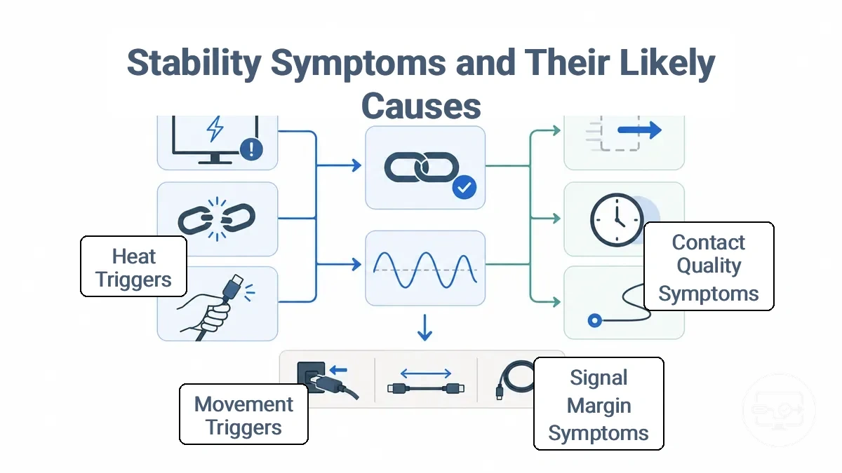
Stability symptoms mapped to likely causes are organized in the table by trigger context and safe first checks, grouping common symptoms with the moment they happen and the probable cause class.
| Symptom | When it happens | Likely cause class | Safe first check | What it suggests |
|---|---|---|---|---|
| Flicker | During cable movement or after repositioning | Contact quality | Re-seat both connector ends | Intermittent pin contact |
| Brief black screen (1‑2 seconds) | After cable is moved or touched | Contact quality | Inspect connector for debris | Partial disconnection |
| Periodic reconnect cycle | Occurs at irregular intervals without movement | Signal margin | Try a shorter cable route | Signal loss over length |
| Works when held | Picture appears or stabilises when cable is held in position | Contact quality | Relieve strain on the connector | Loose fit or worn connector |
| Dropouts when cable is moved | Loss of signal whenever cable is flexed | Contact quality | Reduce bending at the connector end | Internal wire damage or weak latch |
| Stable until touched | Connection works normally but drops on light contact | Contact quality | Clean connector pins gently | Oxidation or micro-debris |
| Intermittent after warm-up | Starts fine, then flickers or drops after 30+ minutes | Signal margin | Allow ventilation near the source | Thermal drift affecting signal integrity |
| Flicker when cable is routed near heat | Flicker appears after cable is placed near a warm surface | Signal margin | Re-route cable away from heat | Heat-related impedance change |
If symptoms persist after these safe checks, the cause may lie outside the cable or connector interface, such as source or display compatibility limits. Deeper evaluation of the signal path may be needed, but the listed checks cover common stability-related causes without requiring tools or settings changes.
Flicker, brief black screens, and periodic reconnect cycles
Flicker, brief black screens, and periodic reconnect cycles often point to a reduced stability margin in the signal path, leading to intermittent renegotiation between the source and display. The flicker and dropouts fixes page provides further troubleshooting steps.
- Random flicker and momentary blackouts typically result from transient interference or marginal cable bandwidth.
- A repeatable reconnect cycle suggests a more consistent trigger such as a loose connection, routing near a noise source, or movement that momentarily breaks the link.
Distinguishing random flicker from a repeatable reconnect cycle helps identify the likely cause: pattern-based dropouts often point to a physical or electrical trigger that can be isolated by checking cable routing, avoiding sharp bends, and minimizing movement near the connector.
If the symptom persists after basic checks, treat it as a stability problem in the path rather than a software or configuration issue.
Position-sensitive loss: “works only when held” and partial plug contact
A connection that works only when held at a certain angle or pressed into place usually points to a loose fit or partial contact between plug and port. This position-sensitive behavior typically points to mechanical stress near the connector neck or a worn strain relief that lets the plug shift under its own weight. The physical alignment of the pins inside the port changes with position; a slight side-load or torque can momentarily restore the connection, but the loose fit remains. The observed effect is intermittent signal loss, and the likely wear location is the connector neck or the port fit itself. Avoid forcing the connection.
Confirm safe, non-destructive observations for position-sensitive loss: “works only when held” and partial plug contact:
- Gently re-seat the cable and see whether the symptom changes.
- Check for wobble at the plug when inserted and see whether the symptom changes.
- Relieve cable weight near the connector and see whether the symptom changes.
- Avoid tight bends near the connector neck and see whether the symptom changes.
- Test the cable without movement and see whether the symptom changes.
Maintenance habits that preserve a stable connection
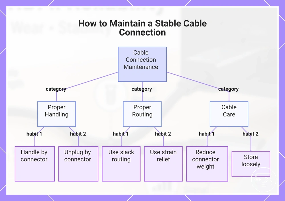
Maintenance habits that preserve a stable connection reduce wear acceleration and help prevent intermittent disconnection caused by cable strain. Handling the cable with care, routing it with enough slack, and regularly inspecting the connector and cable for early signs of wear protect contact quality and reduce strain at common failure points. These habits lower the risk of cumulative damage, but they cannot guarantee indefinite stability or replace deeper repair when severe wear or damage is already present.
Re-seating can help temporarily; strain reduction prevents recurrence. Lasting stability comes from reducing the strain that repeatedly stresses the connector and cable. The following repeatable habits help maintain stable signal flow over time. For a more detailed routine, see the setup steps for stable connections.
- Handling the cable by the connector — reduces twisting force at the plug and prevents a loose fit, which helps maintain contact stability over time.
- Routing the cable with slack — reduces strain on the connector by avoiding tension, which prevents intermittent disconnection from developing.
- Regularly inspecting the cable and connector — catches early signs of wear, such as fraying or bent pins, before they cause intermittent behavior.
- Reducing cable weight at the connector — lightens the load on the port, which can prevent the connector from loosening and causing signal drops.
- Using strain relief near connection points — absorbs movement and prevents concentrated stress on the connector, helping maintain a stable link.
- Keeping the cable free of sharp bends — avoids internal wire damage that can degrade signal quality and cause intermittent faults.
- Unplugging by the connector, not the cable — prevents twisting force that can loosen the fit or damage the cable, reducing the risk of future connection issues.
- Storing the cable loosely when not in use — avoids kinks and pressure that can cause permanent damage, preserving stable connection over time.
This chart shows the key maintenance habits that help preserve a stable cable connection by reducing strain and preventing intermittent disconnection.
Contact hygiene and safe inspection of plugs and ports
Contact hygiene and safe inspection of plugs and ports means checking the contact surface for visible debris, such as lint or dust, that can cause intermittent signals or a loose fit before assuming a deeper fault. A gentle inspection starts with looking at the metal surfaces under good light and stopping if resistance or damage is suspected.
- Visible debris on contact surface → gently blow away loose particles → check if connection stabilizes after re-seating.
- Lint or dust inside port → inspect visually without inserting anything sharp → re-seat and test for intermittent dropouts.
- Discoloration or residue on connector → note area and avoid abrasive wiping → monitor if symptom returns after gentle re-seat.
- Debris on connector pins causing loose fit → inspect visually and gently re-seat → check if connection stabilizes.
- Compacted debris in port opening → use only non-contact methods such as gentle blowing → verify cable clicks fully into place.
Hygiene helps only when contamination is present, not when wear or looseness is the main driver.
Storage and handling practices that reduce wear acceleration
Storage and handling practices that reduce wear acceleration affect how quickly wear accelerates at the connector end and along the cable body, especially through tight coils, sharp bends, and repeated torque at the same point. Small habits reduce cumulative wear, but poor storage — like tight coils or sharp bends — can accelerate strain relief and wear.
- Coil loosely in wide loops — reduces bend radius stress on the cable jacket and internal conductors.
- Pull from the connector head, not the cable body — helps prevent strain at the connector neck and plug fit looseness.
- Avoid twisting the cable during winding — limits torque that can loosen internal connections over time.
- Hang the cable by its mid-section, not the connector end — reduces weight-induced strain on the strain relief and plug fit.
- Store without tight bends near the connector — helps prevent repeated flex fatigue at the most vulnerable point.
- Use a figure-eight winding pattern for longer cables — distributes bends evenly and avoids concentrated torque at one spot.
- Keep the cable free during travel — helps prevent kinks and pinch points that create permanent weak zones.
Reliability-Focused Purchase Signals Without Turning the Page into a Buying Guide
Reliability-focused purchase signals are durability cues that reduce wear risk but do not guarantee performance outcomes. By evaluating construction features such as cable jacket density, connector housing rigidity, and strain relief design, you can identify cables more likely to maintain a stable connection over repeated use.
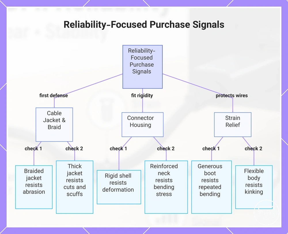
The three primary cue families each address a different wear pathway. Cable jacket and braid act as the first layer of defense against abrasion and everyday handling stress. Connector housing contributes to fit rigidity, reducing the likelihood of a loose connection over time. Strain relief helps protect the internal wires at the cable ends from repeated bending and pull forces. The following checklist organizes these durability signals by cable body, connector housing, and strain relief to guide a reliability-focused evaluation.
- Braided cable jacket → resists abrasion from desk edges and bag storage → can reduce fraying and help maintain stable connection appearance over time
- Thick PVC or TPE jacket → resists cuts and scuffs from daily handling → helps protect internal conductors from exposure and signal loss
- Rigid connector shell → resists deformation when plugged and unplugged → reduces risk of a loose-fit connection that interrupts signal
- Reinforced connector neck → resists bending stress at the plug base → helps protect internal solder joints from cracking and intermittent contact
- Generous strain relief boot → resists repeated bending at cable ends → can reduce wear risk at the most vulnerable point for breakage
- Flexible cable body → resists kinking from tight coiling → helps preserve signal integrity under normal storage and handling stress
- Molded connector housing instead of glued shell → resists separation after repeated plug insertion → helps maintain stable mechanical connection over time
A weak connector housing may lead to a loose fit that interrupts the connection, while a thin jacket can fray under regular use. Inadequate strain relief often results in internal wire breakage after repeated coiling or plugging. Use this checklist to compare candidate cables against these specific wear risks.
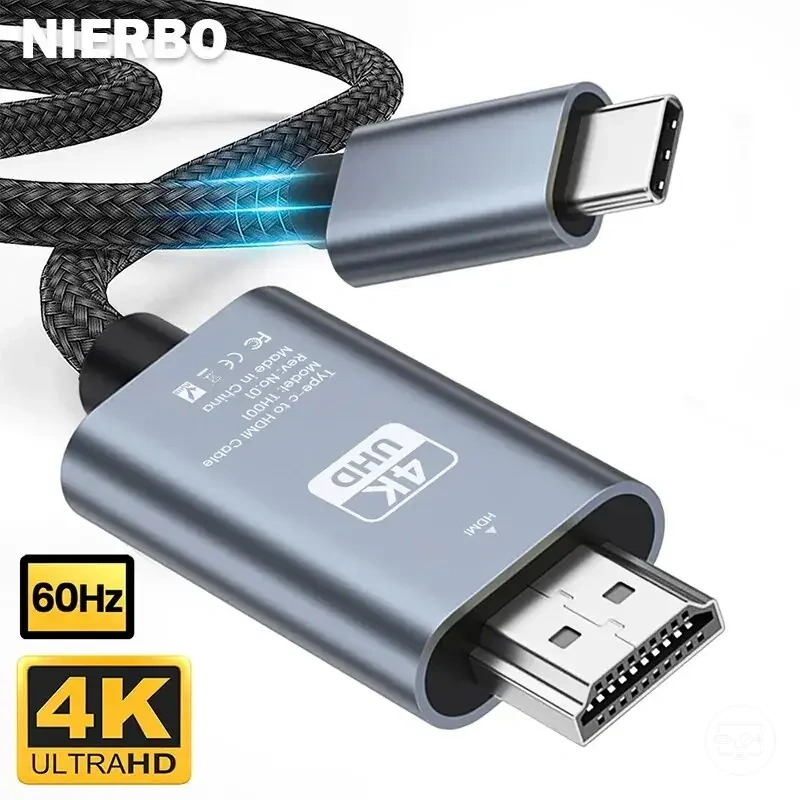
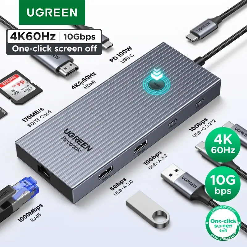
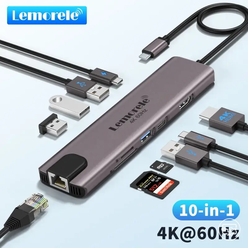
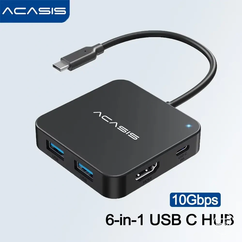
Here are product examples that may make comparison easier. Before buying, always review the compatibility criteria, essential features, and product details.
This chart shows the three main cue families for evaluating cable durability: cable jacket, connector housing, and strain relief, along with specific checks for each.
Durability indicators: braid quality, connector housing rigidity, and strain relief design
Durability indicators are physical design features that influence how a cable manages mechanical stress at the connection point—they are risk reducers, not guarantees, and their effectiveness depends on the specific use conditions.
The durability indicators—braid quality, connector housing rigidity, and strain relief design—each address specific wear modes and contribute to connection stability as follows:
- Braid quality → abrasion and scuffing from repeated handling → can reduce the risk of outer jacket damage and conductor exposure, helping maintain signal path protection.
- Connector housing rigidity → torque and loose fit risk during plug insertion or side-loading → can help maintain consistent contact pressure and alignment, which can help reduce intermittent connection issues.
- Strain relief design → bend stress and cable fatigue from repeated flexing → distributes mechanical forces away from the termination point, helping preserve conductor integrity over time.
When Instability Indicates Replacement Is the Safer Choice
Persistent instability after basic handling and contact checks can indicate non-reversible wear, so replacement is the safer choice when the problem is repeatable and not fixed by cleaning or reseating. Symptoms that persist after checking cable fit, port cleanliness, and tension adjustment often point to underlying wear severity. The decision depends on whether the instability is persistent and follows a repeatable pattern rather than appearing at random.
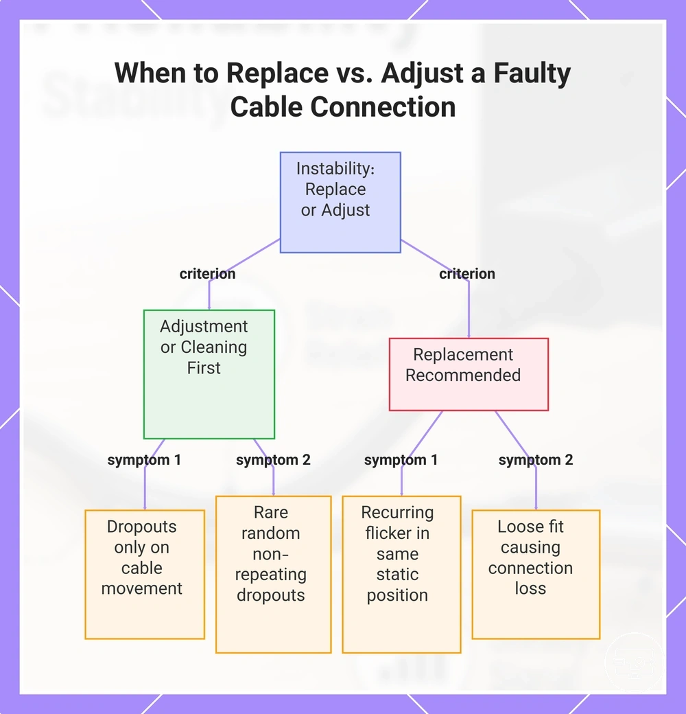
Criteria for choosing between adjustment and replacement fall into two groups. Loose fit that triggers movement-related dropouts indicates progressing wear. Intermittent flicker recurring in the same cable position also points to advancing wear. Contact degradation that worsens over time signals ongoing wear. Rare and random dropouts that do not repeat under consistent conditions may respond to cleaning or reseating. The key distinction is repeatability: intermittent but repeatable symptoms lean toward replacement, while rare and random symptoms may be manageable with simpler steps.
When intermittent dropouts become a frequent, movement-triggered pattern, replacement is the safer choice. Recurring flicker in the same cable position, or a loose fit that consistently breaks the connection under light movement, indicates that contact degradation has reached a point where further adjustment is unlikely to restore reliable performance. The following criteria separate signals that suggest adjustment or cleaning first from those that point toward replacement:
- Intermittent dropouts that only appear when the cable is moved → Adjust/clean first
- Recurring flicker that repeats in the same static position → Consider replacement
- Loose fit that causes connection loss during normal use → Replacement is the safer choice
- Contact degradation visible on the connector pins → Consider replacement
This chart shows how to distinguish symptoms that indicate cable replacement from those that may be resolved by cleaning or reseating.
A quick reliability checklist for deciding whether to adjust, clean, or replace
This checklist helps you choose a safe next step when a cable connection behaves unreliably. Symptom patterns such as intermittent signal loss, flickering, or dropouts often point to a cause class; visible wear on cable or connector confirms direction. Start with the least invasive action, monitor the outcome, then escalate only if needed.
Each outcome guides your next decision. If a simple adjustment stabilizes the connection, no further work is needed. If the symptom returns or remains unchanged, the diagnosis narrows toward cleaning or replacement. The following ordered checklist moves from least invasive actions to higher-confidence replacement signals.
Here are product examples that may make comparison easier. Before buying, always review the compatibility criteria, essential features, and product details.
- Do adjust the cable position to relieve strain at the connector; then watch for signal stability improvement over brief use.
- Do re-seat the plug gently at both the source and display ends; then watch for intermittent dropouts to reduce within a few minutes.
- Do inspect the cable along its full length for kinks, cuts, or crushed sections; then watch for persistent issues after straightening or repositioning.
- Do clean (lightly) the connector contacts with a dry lint-free cloth; then watch for connection firmness over subsequent sessions.
- Do route the cable away from sources of electrical interference or heat; then watch for reduction in flicker or signal loss during normal use.
- Do monitor the symptom pattern for consistency across different ports or devices; then watch for whether the issue tracks the cable or the port.
- Do check the port for debris, bent pins, or looseness; then watch for improvement after gentle cleaning or careful re-insertion.
- Do replace the cable if symptoms persist after all non-invasive steps and visible wear is present; then watch for full resolution with a known-good replacement.